In context of development of era of automobile industry, ignition system of automobiles is also constantly being improved. For example, we have gone from era of most primitive edged weapons to era of firearms. On other hand, it reflects witness of history of development of automotive industry in the general environment.

In an electronic ignition system, ignition signal generator replaces cam in traditional ignition circuit breaker and is used to sense position of piston in cylinder and convert non-electrical piston position signal into an electrical impulse. a signal to send to Ignition Controller to make sure spark plug ignites at correct time. Thus, ignition signal generator is actually a sensor that senses operating state of engine and sends out an ignition signal.
 Ignition type
There are many types, and most widely used are magnetic pulse type, Hall effect type, and photoelectric effect type. Today I will focus on Hall effect formula. A Hall trigger (also known as a Hall element) is a semiconductor substrate with integrated circuits. When a constant voltage is applied to both ends of trigger, a current I passes through it, and in presence of an external magnetic field in direction perpendicular to current, a voltage UH occurs in direction perpendicular to current and This phenomenon is called Hall voltage and is called Hall effect.

A typical example of an electronic ignition circuit (Audi, Santana) using a Hall effect ignition signal generator is shown in figure below.
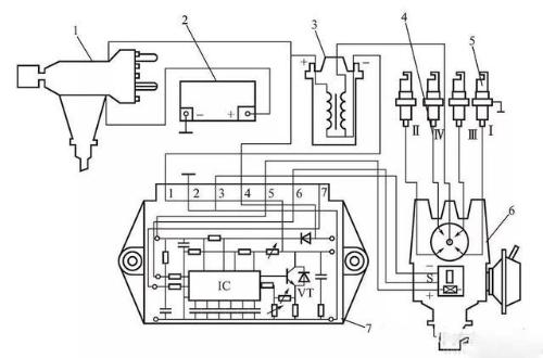
Audi, Santana and other cars mostly use this electronic ignition scheme
1—ignition lock; 2—accumulator; 3—ignition coil; 4—high voltage outlet; 5—spark plug; 6—distributor; 7—electronic igniter.
Characteristics of Hall effect electronic ignition system
The electronic igniter consists of an integrated circuit, a high power switching transistor and related circuits; The Hall Effect Ignition Signal Generator requires a power source, which is provided by electronic igniter. The 7 terminals for connecting electronic igniter circuit are as follows:
Pin 1, output terminal of electronic igniter, is connected to "-" terminal of ignition coil, and its internal part is connected to ground (pin 2) through a powerful VT triode.
Terminal 2 is ground terminal of electronic igniter. When VT triode inside electronic igniter is turned on, primary winding of ignition coil is connected to ground through terminal 2.
Terminals 3 and 5 are electronic igniter power terminals for output to Hall effect ignition signal generator and provide a stable voltage of about 10 V to ignition signal generator during operation; terminal 3 is also a hall effect ignition signal generator. Negative terminal for signal generator signal voltage.
Terminal 4, electronic igniter power terminal, is connected to + terminal of ignition coil and is supplied when ignition is turned on.
Terminal 6 signal voltage terminal (positive pole) that hall effect ignition signal generator outputs to electronic igniter.
Terminal 7, terminal 7 of electronic ignition circuit is not used.
Hall effect electronic ignition system diagram
After ignition is turned on, internal electronics of electronic igniter are powered through terminals #4 and #2, and through terminals #5 and #2 it outputs 10V to Hall Effect Ignition Signal Generator. 3. When distributor shaft rotates, a pulse voltage signal (jumping between 0.4~10V) generated by Hall effect ignition signal generator in distributor is supplied to electronic igniter IC through terminals No. 6 and No. 3 to control VT triode. off, primary winding of ignition coil turns on and off in time, and secondary winding of ignition coil generates high voltage.
Primary current path of electronic ignition circuit: battery + → ignition switch → ignition coil primary → terminal 1 of electronic ignitor → VT in electronic ignitor → terminal 2 of electronic ignitor → ground → battery -.
Hall effect electronic ignition system troubleshooting method
See Table 1 for common malfunction phenomena and possible causes of malfunction of engines with an electronic ignition circuit on effecte Hall, and carry out troubleshooting according to troubleshooting method in Table 2. It is also possible to find faulty components by detecting voltage of low voltage terminal of ignition coil and voltage of each terminal of electronic igniter when ignition is turned on.
Table 2: Hall Effect Electronic Ignition System Circuit Malfunction Diagnosis Method
(Ignition on detection)