01
Removing and installing crankshaft pulley
The Crankshaft Pulley Removal Locking Tool consists of Special Tool 3415 and Adapter Tool CT80009 (as shown in figure below).
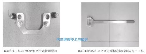
It should be noted that there are currently two types of 3415 on market. Imported model 3415, fixed hole diameter 12mm, matching 12mm bolts can be used. Domestic model S3415, fixing hole diameter is 14mm, bolts corresponding to CT80009 cannot be used, and 12mm or 14mm bolts and nuts can be used for fixing.
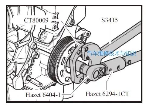
Use 3415 and CT80009 to fix crankshaft pulley, use a HAZET6294-1CT torque wrench (or a wrench that can withstand a maximum torque of 400 Nm or more), and a HAZET6404-1 adapter (or a 21mm hex socket). ) unscrew bolt securing crankshaft pulley (lower figure).
Note. The bolt torque is 150 Nm, after which it is rotated 180° clockwise. To prevent misalignment, when removing crankshaft pulley, use spacer T10368 to contact between original crankshaft pulley and timing pulley and tighten pulley bolts (below).
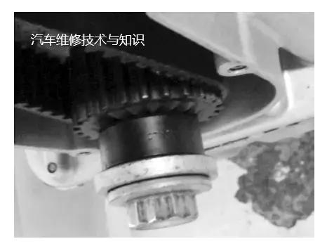
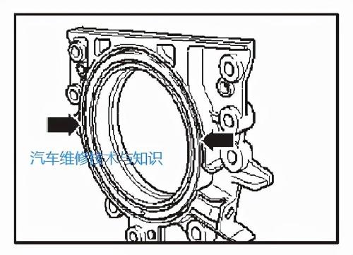
After removing crankshaft pulley and toothed belt, crankshaft pulley (below) can be pulled out.
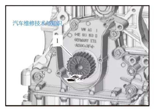
When installing crankshaft pulley, notch on crankshaft pulley must be aligned with notch on crankshaft, otherwise it will damage crankshaft, crankshaft pulley and cause an error in valve timing. .
02
Removing and installing dual-mass flywheel
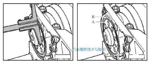
① Insert special tool 3067 at position B on cylinder block to loosen flywheel bolts and remove flywheel. There is only one place to mount flywheel to crankshaft.

② Insert special tool 3067 at position A on cylinder block to tighten flywheel bolts and install flywheel.
03
How to set crankshaft top dead center
Remove retaining bolt from top dead center hole in cylinder block. Screw special tool T10340 onto cylinder block with a torque of 30 Nm and screw it to bottom. Turn crankshaft clockwise to end position (as shown in figure below).
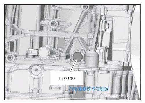
Note: Special pin T10340 is located on side wall of crankshaft, it can only fix crankshaft at top dead center in direction of engine rotation. If T10340 locating pin is not screwed in to end position, crankshaft is not in "top dead center" position of 1st cylinder.
Now do following:
① Unscrew dowel pin.
② Rotate crankshaft clockwise until crankshaft rotates approximately 270° past TDC of cylinder 1.
③ Screw T10340 locating pin to cylinder block with a torque of 30 Nm and screw it to bottom.
④ Turn crankshaft down again in direction of engine rotation.
04
Crankshaft rear oil seal flange installation precautions
① The crankshaft must be locked at TDC of cylinder 1 in direction of engine rotation, and crankshaft flange must be free of grease.
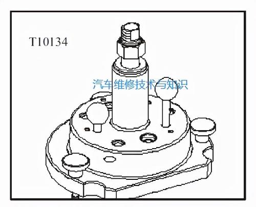
② Special tools such as T10134 (below) must be used.
③ The signal wheel cannot be turned or removed from sealing flange.
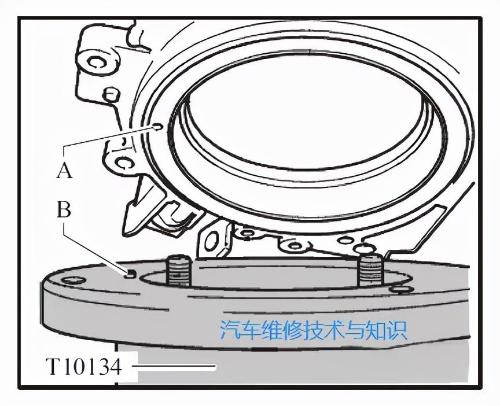
④ The marked hole A on signal wheel must be aligned with locating pin B of T10134 (below).
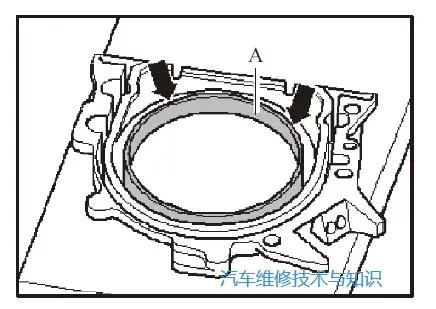
⑤ Place front of sealing flange on a clean surface as shown in figure below, press sealing lip A in direction of arrow and align it flat to ensure that top edge of pulse signal wheel and seal align with front edge of flange .
⑥ Only after signal wheel has been pressed into crankshaft flange, can pressing collar be removed (figure below).
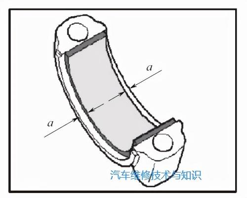
⑦ After installing crankshaft rear oil seal flange into crankshaft using special tool T10134, remove special tool T10134 and oil seal, and measure distance a between crankshaft flange A and signal wheel end face. B with a caliper (as shown in figure below).
Standard value: a=0.5 mm (crankshaft end 0.5 mm higher than signal wheel end)
⑧ If value is too small, keep pressing signal wheel with special tool T10134, if it reaches standard value, continue to install other parts.
05
Disassembly and assembly of piston mechanism
When installing a used piston, arrow on top of piston faces crankshaft pulley. The location of cylinder can be marked with a colored marker. Do not leave on bottom of piston marks of impacts, scratches, nicks (below). Tug A on connecting rod bearing cap points to end of flywheel.
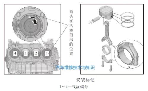
A new connecting rod may not be completely detached. If connecting rod bearing cap cannot be removed by hand, use a soft metal guard (such as copper and other soft materials) to gently clamp connecting rod in a bench vise. , and connect The stem can only be clamped below diameter line through center of circle. Loosen connecting rod bolt 5 turns (lower).
Use a plastic mallet to gently tap connecting rod bearing cap until it comes free.
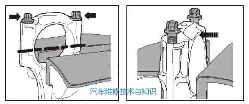
The bearing sleeve must be installed in middle of connecting rod and bearing sleeve cap so that distance a is the same (lower).
Note: Since aluminum alloy cylinder body is easily deformed, crankshaft main bearing cap bolts cannot be loosened or removed, let alone crankshaft.
06
Disassembly and inspection of cylinder head
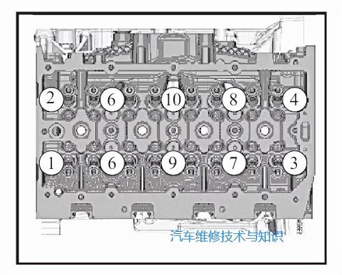
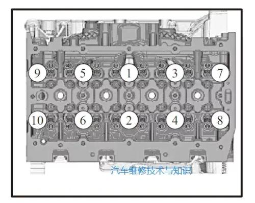
① The sequence for removing cylinder head bolts is shown in figure below, using special tool 3410.
Note. This tool can also be replaced with regular tool HAZET990Slg10.
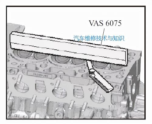
② Cylinder head deformation check: Use VAS6075 500mm ruler and feeler gauge to check whether cylinder head is deformed in several positions, and maximum allowable deformation is 0.05mm (below).
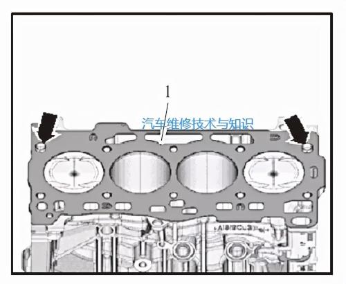
③ Cylinder head gasket 1 must be inserted into cylinder block locating pin (as shown by arrow in figure below), and part number of cylinder gasket can be read.
④ Use T10340 Crankshaft TDC Positioning Tool to position crankshaft at top dead center of No. 1 cylinder piston.
⑤ Replace cylinder head bolts and tighten cylinder head bolts according to serial number sequence and tightening torque requirements shown in the figure.
07
Oil pressure detection
Detection conditions: The oil level is normal, engine oil temperature is above 80°C, i.e. cooling fan works once.
① Use VAG1342 oil pressure detection device to detect low oil pressure switch and engine oil pressure.
② Idling oil pressure: 0.6 bar minimum.
③ Oil pressure at 2000 rpm: minimum overpressure 1.5 bar.
④ Oil pressure at 4500 rpm: minimum overpressure 2.8 bar.
Note. The oil pressure in a new car must be maintained at 3.3 bar for 1000 km before driving.